![]()
THE DETECTION OF BURIED OBJECTS IN THE SAND USING ACOUSTICS
RCP Evans (PhD Student), TG Leighton (Principal Investigator)
For detailed reports, click here
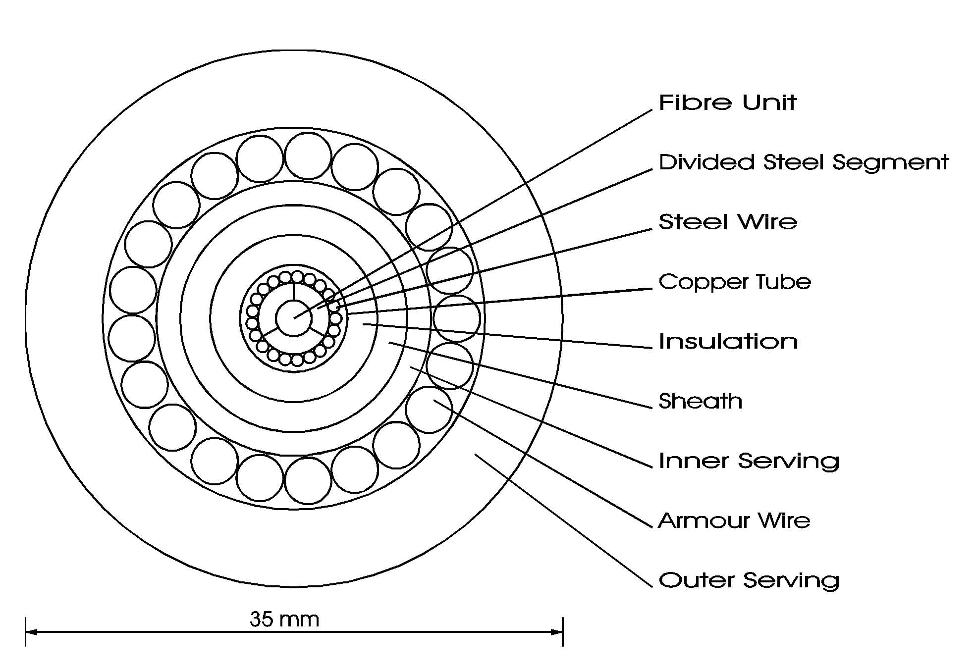
This study has focused on a range of techniques to facilitate the detection of objects buried in submerged sediment. Particular emphasis was given to the detection of objects resembling lightweight submarine cables, i.e. polyethylene-jacketed fibre optic cables (similar to that shown in cross-section in Figure 1) but with a much-reduced metal content. This anticipates a technological challenge that will face the telecommunications industry in the near future.
|
Figure 1. The structure of a typical lightweight fibre optic cable (figure courtesy of Cable & Wireless, private communication). |
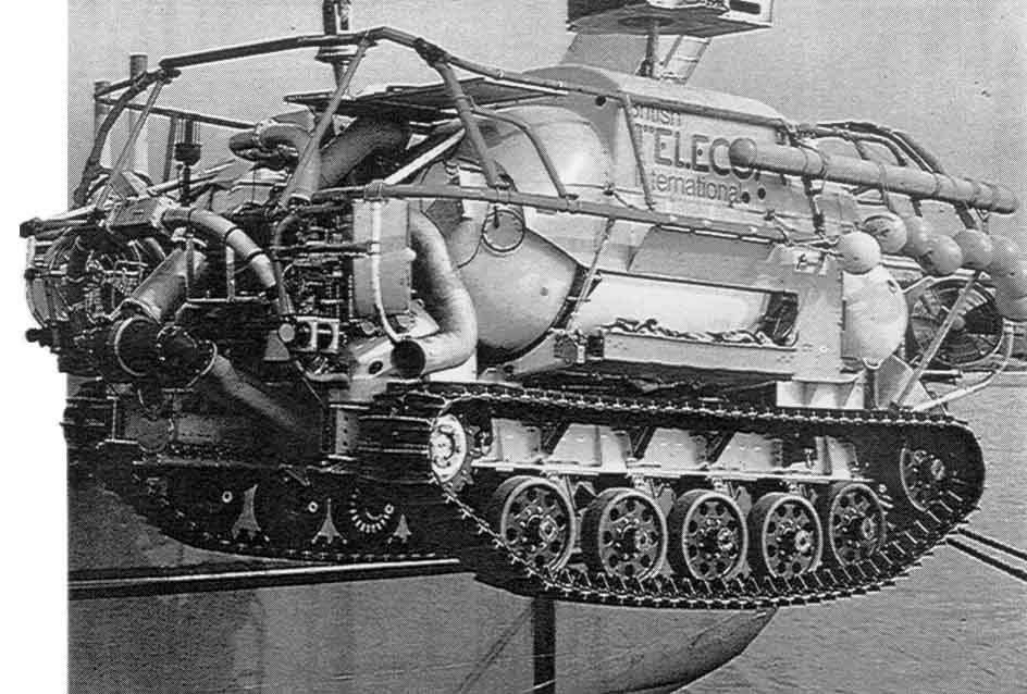
The overall requirement was to identify a system suitable for deployment on a seabed-crawling remotely operated vehicle, ROV, (similar to that shown in Figure 2), and capable of returning information to enable the location and tracking of cables buried to a depth of up to 1 m in the seabed. The detection system had to be able to penetrate the sediment without being significantly affected by suspended material and able to distinguish the cable uniquely from the surrounding environment.
|
Figure 2. The 3 m long ‘Seadog’ tracked underwater vehicle is used for cable burial, tracking and repair at a maximum sea depth of 275 m. (From ROV Review 1993-94, WAVES magazine, Windate Enterprises Inc., 5th Edition.) |
OPTIMAL FILTERING
The feasibility of using an acoustic detection system is substantiated by the wide range of underwater acoustic imaging systems that are commercially available. To date, however, sub-bottom imaging systems have been limited by the densely cluttered nature of the environment. The choice of output waveform depends on the requirements of penetration depth, resolution and known target characteristics. Pulsed wave systems are capable of accurate range measurement and resolution. In addition, pulse expansion / compression techniques can be used to achieve a high total output power. When information regarding the nature of the transmitted waveform, the target and noise and clutter is available, a filter can be designed to select and modify the shape of the scattered signal to maximize the likelihood of detection.
Resolution is known to be a function of signal bandwidth, and not of pulse width. Therefore, although this filter can be applied to any waveform, certain waveforms give rise to less ambiguous measurements. Where it is known that the transmitted signal will be unaffected by a Doppler displacement, the linear-FM pulse approximates the optimum waveform.
ATTENUATION
In order that an optimal frequency band can be chosen and that the filter can be fine-tuned to match the target signal at the receiver, the attenuating effect of the medium and the scattering characteristic of the target must be known. The total acoustic path length for an ROV-mounted detection system will be less than 6 m. To resolve a 20 mm diameter target requires a waveform in the 10 - 100 kHz frequency range. At this distance and frequency the attenuating effect of seawater and suspended material is negligible. Conversely, the attenuating effect of the sediment is significant. In sandy sediments and in the frequency band of interest, historical data suggests that attenuation is approximately dependent on the first power of frequency. The attenuation coefficient of common sand was measured in the laboratory.
The principal targets considered in this study are, in effect, infinitely long elastic cylinders surrounded by a homogeneous fluid medium. From the literature the agreement between partial wave theory and experiment is seen to be excellent.
Measurements of attenuation in saturated sand have confirmed that it varies approximately with the first power of frequency over the range of frequencies being considered. Measurements of the scattering characteristic of cylindrical objects in water have confirmed that the theory of resonant scattering matches observation. This theory can be applied to the detection of buried objects provided that the burial medium behaves like a fluid at sufficiently high frequencies.
The operating frequency band for the output waveform is selected by combining the attenuation and background noise spectra in the medium, the scattering function of the target and the transfer function of the transducers. Attenuation and the target scattering function have been considered in some detail. (The transfer function of the transducers and the background noise spectrum can be easily obtained and, therefore, will not been considered any further.)
The optimal filter is determined in a similar way to the operating frequency band, i.e. by combining the output waveform, attenuation, background noise, target scattering function and transducer transfer function. (The target estimate can be improved further by averaging the filter outputs obtained with the transducers at a range of positions. This reduces the overall contribution made by clutter.)
An investigation has been performed using a water tank, part-filled with common sand, and a bistatic arrangement of focused transducers inclined at a grazing angle of 57° +/- 1°. The source and receiver were used to insonify and receive the acoustic energy scattered from around discrete points within the sediment. An automated control system was developed to position the transducers and to handle the data acquisition process. Details can be found here.
A range of cylindrical objects of various sizes and materials were separately buried along the width of the laboratory tank to a depth of up to 30 cm +/- 3 cm. A 20 mm diameter polyethylene cylinder was of special interest because of its similarity to submarine cables.
The transducers were used to collect acoustic data from sample-planes extending vertically upwards from the base of the tank (z-direction) and horizontally along the length of the tank (x-direction). The bandwidth of the linear-FM output pulse was 50-120 kHz. This made best use of the dynamic range of the hydrophones.
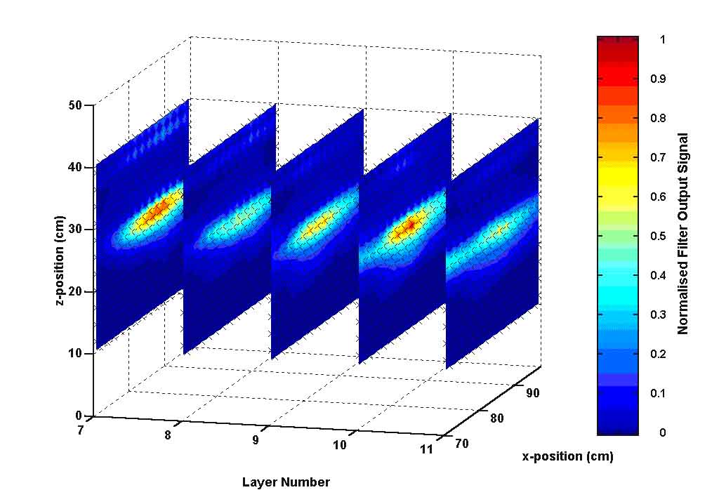
An example of the time-windowed peak of the squared output of the optimal filter is shown below. This result clearly shows the presence of an object, the polyethylene cylinder, buried near the middle of the sample plane. The main effort of this study has focused on a means of locating specific buried objects. For cables an additional means of detection is made possible by their polarized geometry.
Targets located in successive sample-planes may appear to form a consistent line when they are stacked in series. This is a clear indication of an extended object, e.g. a cable (Figure 3).
|
|
Figure 3. The normalised, peak-squared, elastic-response-optimised, inverse filter output from a target region containing a polyethylene cylinder (SNR = 20.3 dB). |
The detection of cylindrical objects of low acoustic contrast buried in the seabed is complicated by the densely cluttered nature and the relatively high attenuating effect of the sub-bottom environment.
Optimal filtering is known to be a powerful technique for the separation of known signals from high levels of background noise and clutter. Excellent laboratory results have confirmed the usefulness of the technique in this application.
Careful consideration must be given to the attenuation and noise in the medium and the scattering characteristic of the target in order that the filter can be optimized effectively and an appropriate detecting waveform can be designed.
This work was supported by Cable & Wireless and the Engineering and Physical Sciences Research Council.
(Page last updated by T. G. Leighton, 23 May 2006)