|
| |
|
Facilities
|
|
The facilities used by the Virtual
Acoustic Project are located at the Rayleigh Laboratories and are operated
by ISVR Consultancy Services. The laboratories are well served with comprehensive
control and preparation areas. A wide range of modern, highly specialised
instrumentation is available.
|
|
Anechoic chamber
An anechoic chamber is a room in
which the walls, floor and ceiling are lined with sound absorbing material,
usually foam or glass-fibre wedges. The lining prevents the reflection
of sound from the room boundaries so that 'free-field' conditions exist.
The room sounds very 'dead'. Sound measurements are not influenced by the
room surfaces, and an anechoic room is an ideal environment for many standard
tests such as the measurement of the sound power of a machine, or measurements
of microphone and loudspeaker frequency responses.
The Large Anechoic Room at ISVR
is one of the largest in the UK. It was extensively refurbished during
1995/96 and the original polyurethane foam wedges were replaced with glass
fibre wedges.
Construction
Built as a box within a box, it
is acoustically isolated from the rest of the building and adjacent chambers
by an air gap all around and is supported on vibration isolation mounts.
The reinforced concrete walls are 305 mm thick.
|
 |
|
Wall Lining
There are over 8,000 non-flammable
glass-fibre cored wedges, extending 910 mm from the walls, floor and ceiling.
Free-field conditions exist at frequencies above 80 Hz.
Dimensions
Without wedges the bare chamber
is 9.15 m x 9.15 m x 7.32 m, volume 611 cubic metres. The usable space
between the wedges is 7.33 m x 7.33 m x 5.50 m, giving a usable volume
of 295 cubic metres
Access
Double doors 2.0 m wide x 2.4 m
high
Flooring
A grid of removable floor panels
can support a spread load of several tons with a minimum of interference
with the anechoic nature of the chamber. An optional floor of varnished
chipboard is available for measurements requiring a free field above a
reflecting plane (hemi-anechoic conditions).
Listening room
This has been designed to meet the
requirements of IEC 268-13 and BS 4860:Part 13 for standard listening conditions
in which loudspeakers or recordings can be assessed subjectively. The acoustics
are similar to a living room in a house rather than the 'deadness' of an
anechoic room. Adjustable absorbent panels on the walls allow the reverberation
time to be varied. An acoustically-transparent curtain near the front of
the room allows 'blind' comparisons of loudspeakers.
Dimensions
6.52 m x 4.20 m x 2.68
m high, Volume 73 cubic metres
HRTFs measurement equipment
Measurements are carried out in
the large anechoic chamber of the ISVR.
|
|
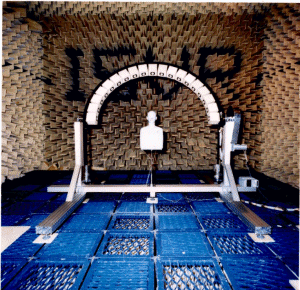
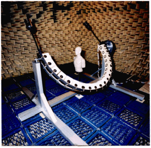
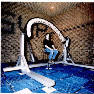
Motorised rotating arc
Two
arcs were designed and built: a smaller one with a radius of 1.15 m and
a larger one with a radius of 1.6 m. The resulting distance between the
cone of the loudspeaker and the microphone positioned at the entrance to
the blocked ear canal of the pinna is exactly 1 m. 19 loudspeakers are
mounted at an equal spacing of 10º between each other. It is estimated
that the positional error due to the radius of the arc and its curvature
is less than 1 cm, and due to the spacing between the speakers is less
than 0.5°.
The rotation of the arc is achieved
by a transmission chain between the arc and a step motor. When the system
was calibrated it was found that every pulse to the step motor would rotate
the arc by 1/10932 of 1º. (i.e. in order to rotate the arc by 180º,
1456789 pulses are required. The rotation of the arc in this case takes
only 4 minutes.
The effect of reflections due to
adjacent loudspeakers mounted on the arc was investigated by covering all
loudspeakers, except the one used for the measurement, with absorbent material,
and also when the same loudspeaker was used for measurement of baffled
pinnae in the anechoic chamber without the arc and all the loudspeakers.
Differences at frequencies below 10 kHz were less than 1 dB, and variations
up to 2 dB were noticed at higher frequencies.
|
 |
|
Baffled pinna measurements
A large baffle was constructed
out of thick plywood. Its large dimensions (with a maximum width of 2.3
m, and a maximum height of 2.4 m) ensured that the measurements of the
acoustical response of the pinna are not distorted due to diffraction and
reflection from the boundaries of the baffle. In the centre of the baffle
a circular aluminium plate was positioned, able to rotate around its centre,
and a rectangular opening enables the positioning of the artificial pinnae.
The response of human pinnae can also be measured when subjects sit behind
the baffle but these are not included in this study. An additional circular
plate included an opening for the holding Electret microphone, flush mounted
with the baffle plane. This was used for equalisation of the transducers
for each source position in space.
MLSSA system
The Maximum Length Sequence System
Analyzer (MLSSA) has been used widely in recent years in HRTF measurements.
The MLS method offers a number of advantages compared to traditional frequency
and time domain techniques. With the accurate positioning capability of
the transducers with respect to the head/pinnae in our measurement set-up,
a single channel measurement system is sufficient. Consecutive measurements
with all loudspeakers and two microphones (in the case of KEMAR) were used
to generate a matrix of impulse responses capturing the space with a dense
resolution.
|
|

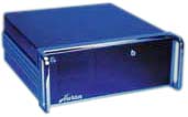
Localisation measurement equipment |

Huron 20 Digital Audio Convolution
Workstation |
|
|
|

