|
|
|
Cross-talk cancellation for
a loudspeaker span of 10 deg.
Frequency domain response with
the DBEM
The method of calculating the sound
field with a numerical solution includes the following stages:
-
The pressure at each of the blocked
ear-canals is calculated due to a single source at a time. The position
of the source is equivalent to the position of a real source.
-
A matrix of the ‘electro-acoustic’
response is obtained (2x2 for two speakers and two ears, and 4x4 for four
speakers and four ears). e.g. C12 is the response at ear no. 1 due to source
no. 2.
-
A desired signal is determined. Generally
“0“ pressure is assigned to one of the ears, and “1“ to the other ear,
i.e. d=[1 0]T for a 2x2 system, where d is the
vector of the desired signals.
-
Each source is filtered (via appropriately
designed inverse filters) to produce the desired signals with a table of
complex pressure values at each frequency. The regularisation value was
chosen for each head and loudspeaker arrangement as described below. In
all cases the regularisation parameter was chosen to be 0.001 to remove
ill conditioning due to symmetric acoustic paths.
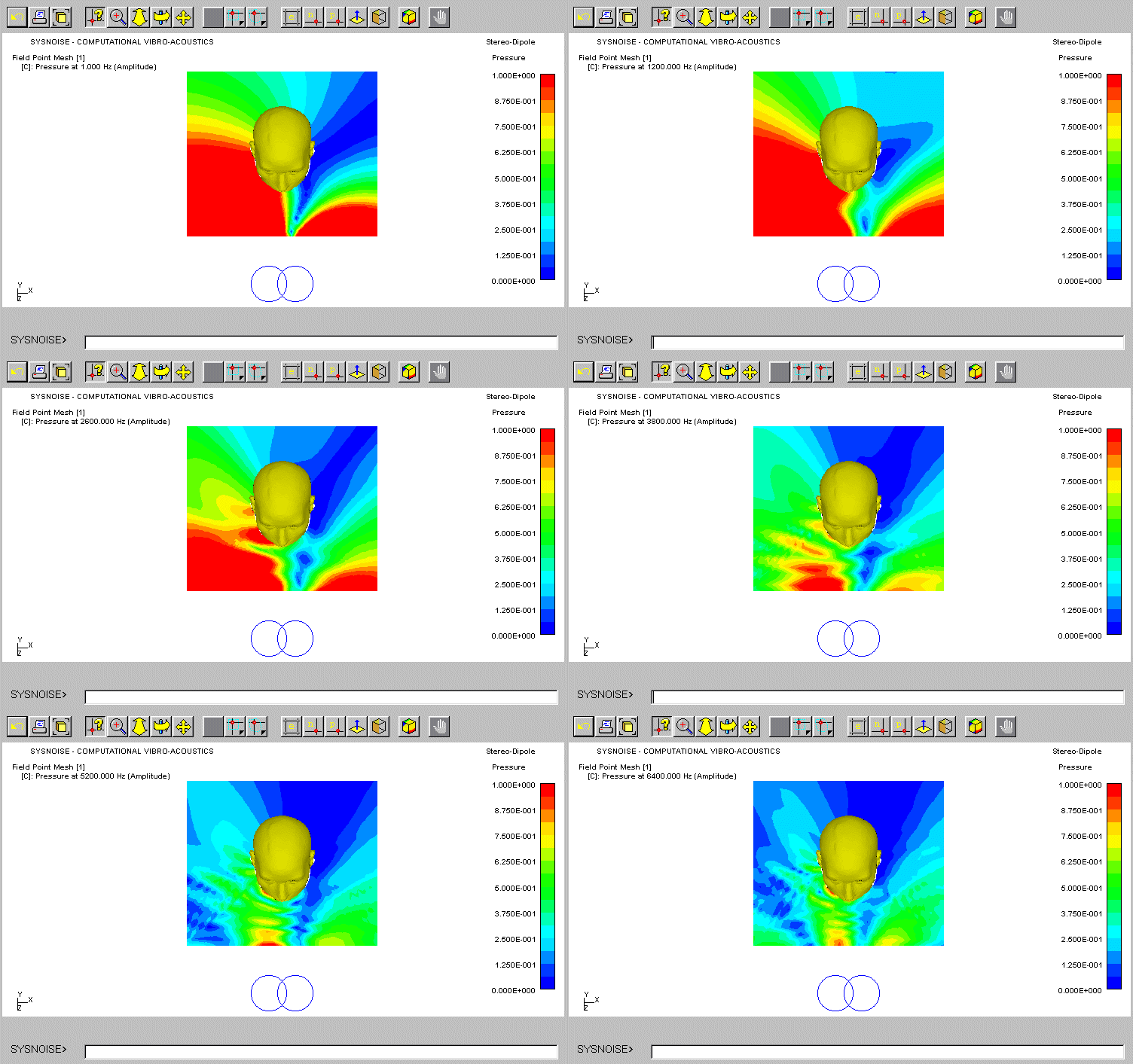
Our goal is to control locally the
pressure at the entrance to the ear canal only. Our cross-talk cancellation
matrix is designed to produce zero pressure at the right ear of KEMAR and
pressure of unity in its left ear. It is seen that the proximity of the
speaker divides the pressure zones to the right and left sides of the head.
As frequency increases the equalisation zone on the head is reduced, and
only accurate attenuation is obtained at the entrance to the ear canal
and within the concha. The scale is linear where red is limited to unity
and blue to zero pressure. Note that this simulation is ideal, and it does
not highlight the problem of loudspeaker behaviour due to the ill-conditioning
at low frequencies.
The animation shows the resulting
sound field around the head in the frequency domain for the same filtered
signals as used in the previous figure. The characteristic common to all
frequencies is the symmetry with respect to the centre axis between the
sources, i.e. the separation between the right and left channels is preserved
even if the head is not positioned in the exact 'sweet-spot' but along
this axis.

|